Drillholes
This
Interactive Viewer
On the Drillhole tab, in the Database group, you can now select an option to View the Collar, Survey, Interval and Event files in a Drillhole Database.
![]()
Hole selection is synchronised across the different panes of the Viewer and hole colours are customisable, making it easy to differentiate between and correlate holes across different panes.
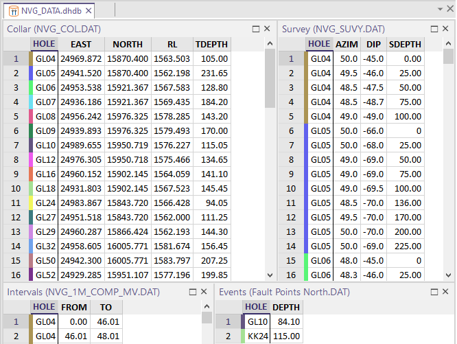
Visibility options allow the records which are not currently selected to be hidden or shadowed, making it easier to focus on the details of a particular subset of holes.
![]()
![]()
![]()
On the Drillhole | Viewer tab, in the Window group, you can use the Show Panes menu to set which panes are visible in the Viewer.
![]()
Validation/Errors
When you validate a Drillhole Database, if errors are detected and you choose to Fix errors, a Validation/Errors pane is loaded in the Viewer and is synchronised with other panes.
Error rows can be grouped according to the severity of the error.
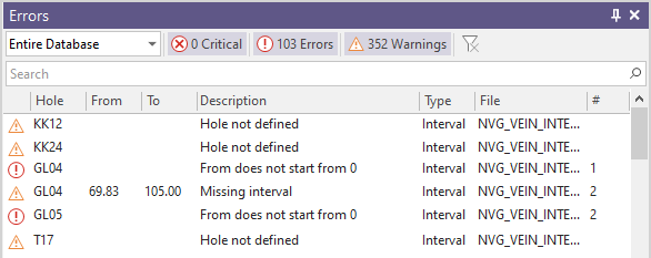
Rows in the file panes of the Viewer which match to the errors shown in the Validation/Errors pane can be colour-coded as part of your Viewer Options:
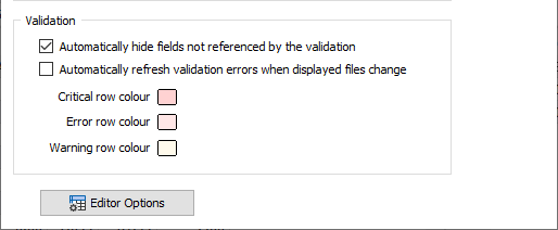
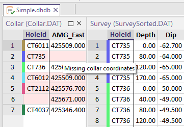
When the mouse is hovered over the corresponding row of a file in the Viewer, a tooltip detailing the error or warning is shown:
New "Planning" Layer
Drillhole Planning now uses a special "Planning layer" to create planned holes. The planning workflow has also been streamlined and there are now just two (From Collar and From Target) trace creation tools which provide the option to create either a curved or a straight hole.
![]()
A new Load Drillholes into Plan option can be used to load the holes in a Trace String file and/or a Drillhole Database as the basis for planning:
![]()
A new Create Pattern tool can be used to define a drillhole pattern and add it to the planning layer. The holes of the pattern can be adjusted interactively:
![]()
When you click Finish Plan to save the planned holes, the holes are enumerated (using a default “PDH001, 2, 3, etc“ identifier for each hole) and saved to a Collar file and a Survey file. The created traces can be auto loaded in Vizex.
If you also choose to save the plan to a Drillhole Database, the database can be loaded at a later date using the Load Drillholes into Plan option.
![]()
Interval Selection
On the Drillhole tab, in the Data group, a new Interval Selection tool to streamline the selection of intervals with a specific code.
![]()
The tool activates Paintbrush Selection mode and prompts you to select an interval to filter the selection to. The tool detects the field that the intervals are colour-coded or hatched by (in this example, LITH code) and then prompts you to use the "paintbrush" to draw a ribbon over the intervals you want to select:

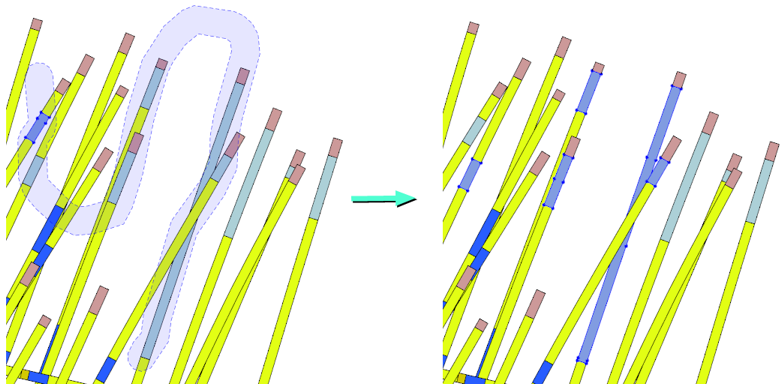
Up and Down arrows can be used to increase or decrease the thickness of the brush stroke. Right-click to end the selection. You can also use the CTRL key with the mouse to make multiple selections. The holes and intervals you have selected are listed in the Properties pane, where they can be edited.
Show Hole in Linked Image Viewer
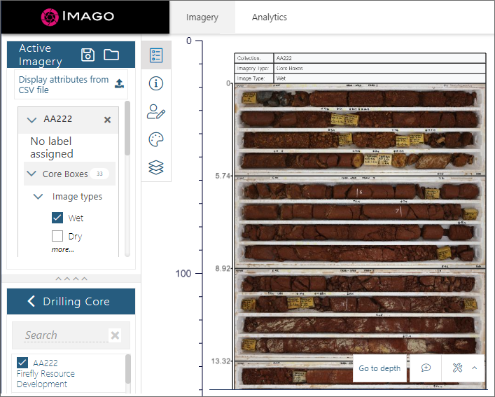
Recently-introduced Imago linking functionality (accessed via the Vizex right-click Show Hole in Linked Image Viewer menu option) has now been extended to include Drillhole Interval (Label, Hatch, Graph) and Event layers.
![]() Imago linking offers clients the ability to link to downhole imagery and view and navigate that imagery using the Light Table on its Imago Portal Imagery page.
Imago linking offers clients the ability to link to downhole imagery and view and navigate that imagery using the Light Table on its Imago Portal Imagery page.
Geology Compositing
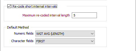
An option to Re-code short internal intervals less than or equal to a specified Maximum re-coded interval length has been to the Drillhole Geology Compositing function. This will simplify the compositing process by merging longer-length intervals either side of the short intervals.
Downhole Compositing
The performance of the Downhole Compositing process has been improved when a large number of drillholes are being processed and the Generate Downhole Coordinates option is selected on the Output tab of the form.
![]()
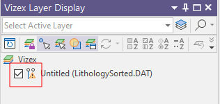
View Invalid Holes
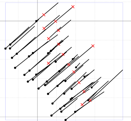
When creating or editing a Drillhole Database, if you choose to ignore errors during auto-validation, holes where the hole depth is missing or is negative are added to the database and flagged as invalid:
When displaying a Drillhole Trace in Vizex, holes which are invalid are displayed with a red cross at the collar and a warning icon is also added to the layer to show that the displayed data contains errors.
Drillhole & Drillhole Database Validation
When setting validation options in Drillhole | Validation | Validate Drillhole (or Drillhole | Validation | Validate Drillhole Database), a check that the holes defined in a Survey file, Interval file or Event file are also defined in the Collar file is now mandatory.
If enabled, the "Check for holes missing" check box options (or the "Check for missing holes" check box in the case of a Drillhole Database) will also check that holes in the Collar file are present in the Survey/Interval/Event file.
In previous versions, when these check boxes were selected, a check was made that holes defined in a Survey/Interval/Event file were also defined in the Collar file AND vice versa.